News & Resources
 Due to the heightened demand for bandwidth in In-building systems, C-Band, 3.7GHz to 3.98GHz, Band n77, is widely being deployed in DAS networks. In addition, CBRS spectrum (3.55GHz to 3.7GHz, Band 48) and DoD spectrum (3.45GHz to 3.55GHz) is also being deployed. While not all of this spectrum is available commercially yet, the passive infrastructure for DAS is tested for future-proofing the DAS networks. ECSite has been involved in providing software to automate the data collection for over 25 C-Band networks. We have planned a series of articles to share some of the lessons learned in C-Band passive infrastructure deployments:
- Cable Sweeping for C-Band
- PIM Testing for C-Band
- Diplexing existing passive networks for C-Band
- Performance verification for C-Band networks
In this article, we present the challenges of C-Band sweep testing and ways to mitigate them.
It all starts with the cable!
At the beginning of the project, during iBwave design, the designer makes a choice for the coax cables. More often than not, a ½” plenum-rated cable is used for in-building applications. The designer needs to pay careful attention to the datasheet for the cables. Does the cable specify and/or meet the return loss/VSWR specs required by the operator? For example, a Verizon Network Advisory suggests a 24dB return loss for passive infrastructure. Most commonly used cables only specify a VSWR spec up to 2.7GHz. Here are some commonly used coax cables and their VSWR spec.
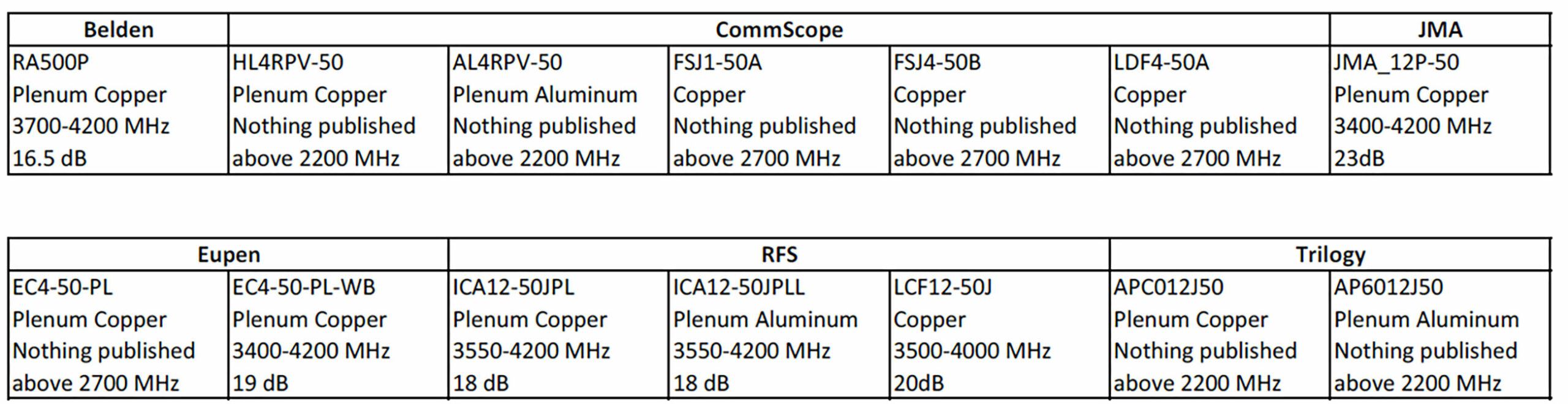
There are several cables in this table that don’t have any return loss specifications for frequencies in C-band. In some cases, the RL spec is 18dB. With the cable spec at 18dB it will be very difficult to achieve a 24dB return loss spec for the cable assembly. If the specs are not published, does it mean that the cable may not perform? In our experience, we have seen cables even without this specification working well, provided all other connector preparations are taken into account (described in the next section). Regardless, if the cables you choose don’t have a published spec, you are on your own. Do not expect the cable manufacturer to support you with your return loss problems!
An additional aspect to consider is the discrepancy between cable data sheets and iBwave Vex files with respect to insertion loss. One of our customers reported testing a 100’ length of a popular cable in C-band and measured the IL to be 0.5dB worse than the spec. It is recommended that you sample a few cables and measure the insertion loss to reflect the link budget appropriately before beginning construction. Datasheets and Vex files are ‘indicative’ of some number of samples in a lab environment and may not match the field. As they say Trust, but Verify!
And then there are connectors and connectorization!
Compared to frequencies below 2.7GHz, C-band frequencies are very sensitive to the connectorization process. Some connector vendors do not publish how their connectors perform with certain types of cables. In those cases, you are on your own again. Fortunately, some manufacturers like JMA Wireless do publish cable/connector compatibility information. Here is a link to JMA’s connector matrix which shows what cables are supported by what connectors – please note that, this does not cover the performance of the cable + connector assembly, outside of JMA cables and JMA connectors.
DAS Connector Matrix (jmawireless.com)
A common conversation we have with the GCs is “Have you been trained on connectorizaton for these types of cables and these types of connectors?”. A common answer is “It has been a while”. Recently, in a call with JMA tech support, the tech support asked if they have a vacuum cleaner and an adapter for the vacuum cleaner to remove all the shards during connector prep. That was entirely new to the GC team. It is imperative to follow all the steps, use the right tools, and have appropriate training for the connectorization process. While ECSite does not offer any direct training for the connectorization process, many times, during in-field audits, we have found C-Band sweep test failures attributed to poor connectorization. Please reach out to the connector vendor with the correct cable model and get yourself trained before you connectorize 100s of cables and test later to find out if the C-band fails.
Here is a link to a video for installing JMA ½” annular plenum connectors: https://www.youtube.com/watch?v=nOOfs0nEBos
While is it industry practice to have the ‘connector’ team separate from the testing team, for C-Band, before connectorizaton of 100s of cables, it is best to sweep and PIM test various lengths of cables after the connectors have been put on to ensure that we don’t have any issues downstream.
C-Band Test Frequencies:
The C-Band Frequencies in the US (band n77) are between 3.7GHz to 3.98GHz across the carriers. If you only want to sweep C-Band, then testing between 3.7GHz to 4GHz is recommended. However, while you are at it, including the DoT and CBRS bands and sweep testing from 3.45GHz to 4.0GHz has not caused any additional issues.
Test Equipment, Tools, and Accessories
For C-Band testing, the following instruments and models support C-Band testing. We also note which instruments are supported by ECSite software. Equipment that has a stop frequency of up to 4GHz is required.
- Anritsu Sitemaster S3xE. Note that S332E supports C-Band and so does S362E. While the S331L and S331P also support C-Band testing, they are not supported by ECSite software.
- Rohde Schwarz R&S ZPH P2 (4GHz) or if you have the P1 model, you can software upgrade to ZPH-B4 to support upto 4GHz
- Keysight FieldFox 99xxA, 99xxB – most field foxes support up to 4GHz for Cable and Antenna Analyzer
- Kaelus iVA – Kaelus iVA supports only 2.7GHz and does not support C-Band. Kaelus has iWA that goes up to 6GHz in their roadmap. Due to the speed of testing of Kaelus iVA with ECSite in DAS applications, we’ve seen a use model where one crew uses the Kaelus iVA for testing up to 2.7GHz and another crew follows using a Sitemaster/R&S/FieldFox for C-Band testing. This has proven to be an effective strategy as well.
ECSite has found that performing a FlexCal on Anritsu’s from 617MHz to 4GHz does not seem to affect the performance (this saves time to have to use STD cal for every frequency).
Perform an OSL calibration at the beginning of the day and/or if temperature changes.
Tools:
It is essential that the technicians use alcohol swabs to clean the connectors and appropriate torque wrenches to torque them to components. Without an appropriate torque wrench, we’ve seen PIM issues in various bands. If the cable is left to be connected to passives later, it is better to put a dustcap on the connectors.
Test Standards and Adapters
Most DAS deployments today use 4.3-10 connectors for coax and passives. Most test equipment is manufactured with N-type connectors. We need to ensure that the factory calibration is current on all test equipment. Some test equipment needs to be calibrated with the Phase Stable Cable using an Open/Short/Load termination. It is common practice to use adapters to go from N-Type to 4.3-10 connectors. Since the return loss specs are tight with C-Band, it is best to avoid any adapters. The adapters exhibit cascaded return loss effects and bring down the overall return loss. A recommended configuration for test setup is shown below. While it may be expensive to get a 4.3-10 OSL, it is strongly advised to use the 4.3-10 OSL for calibration and testing.
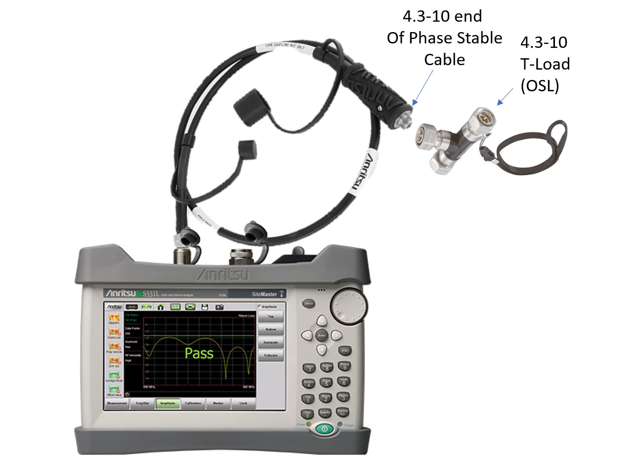
Calibration Setup
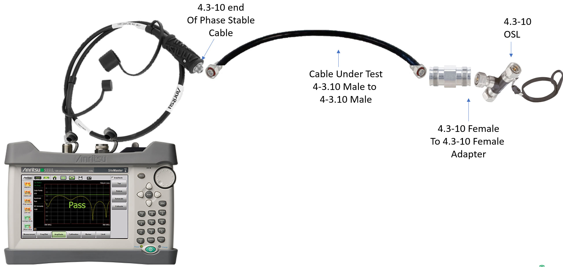
Test Setup
While we recommended not to use any adapters, based on the commonly available components, there will be one adapter needed based on the type of the OSL. If you buy a female OSL (compared to what is shown in this setup), you’ll need an adapter during calibration.
Some part numbers that have worked well:
- Anritsu 15N43F50-3.0C: Test Port Extension Cable, Armored, 3 meters, DC to 6 GHz, N(m) to 4.3-10 (f)
- Anritsu 2000-1915-R: DC-6GHz 4.3-10(M) OSL cal kit
- Rosenberger 64S36R-MSOS3 4.3-10 male calibration kit
- Pasternack PE91386 Low PIM 4.3-10 Female to 4.3-10 Female adapters (I’d recommend a few of these in the kit, $129 each). Ensure you change the adapters once every 2 months.
Some common causes of failures due to Test Equipment:
- Use of a series of adapters. If you have an N-N Phase stable cable and an N-type OSL, you won’t need any adapters for calibration, but you will have to use 2 adapters for the testing with one adapter on each end. The adapters are not designed to be used/replaced for 1000s of insertions and are primarily intended for lab purposes.
- Use of ‘blue jumper cables’ as ‘phase stable cables’. While the ‘blue jumper’ cables can serve the purpose, they are not ‘phase stable’. Temperature changes around the cable will affect your calibration. If you do end up using the jumper cables as your ‘phase stable cable’, please make sure you have a whole bag of them and you replace them fairly often to ensure quality results.
Again, it is important that any adapters and the OSL be cleaned with alcohol swabs periodically.
What are some good return loss limits for C-Band?
ECSite software has been used in over 25 venues to test C-band. Based on the cables and connectors used in these projects, the following RL limits have been set and found passing for those specific cables. The table below shows the number of cables across these projects and their return loss limits, as set up in ECSite software. There have been cases where the limit was set to 20dB and later adjusted to 18dB due to a large number of failures in C-band return loss at 20dB for those projects.
.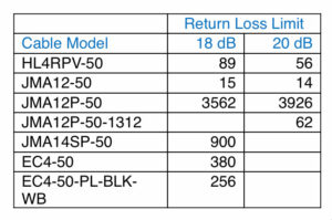
In our opinion, for cable return loss, an 18dB limit in C-band is acceptable. 18dB return loss corresponds to a 98.5% transmission efficiency and for a 1W transmission, the expected power loss due to 18dB return loss on the cable is ~15mW! In other words, 985mW will be transmitted and only 15mW will be “wasted”.
In the same vein, we often get asked, “I am at 17.85dB for an 18dB RL limit. Can you make the results show as a ‘PASS’?” We always respond with “We need to draw a line somewhere and it has to be a consistent line”. Correct connectorization practices, fewer adapters, cleaning the connectors etc. usually fix these marginal issues.
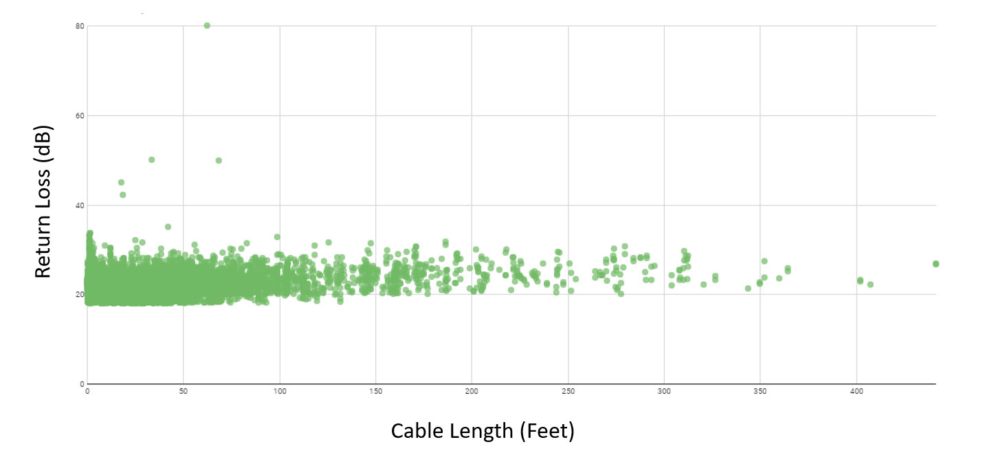
How is the C-Band return loss affected by the length of the cables?
Longer cables have a larger return loss and can sometimes mask RL issues. Cables longer than 400 feet should be tested for return loss from both sides of the cable. It is advisable to do a DTF to a short and use that length to determine the insertion loss. Below is a plot that shows cable lengths versus return loss in C-Band. Since this is a return loss measurement, we get results independent of the length. Typically longer cables should have better return loss.
Recommended Tests for C-Band
- Return loss to a Load
- DTF to a Load (to validate the connectors)
- DTF to a Short (for measuring length, this can be skipped if other bands have been DTF tested )
- Insertion Loss /Cable Loss to a Short/Open (to validate the connectors and any cable bends)
A Note about ECSite Software and Test Plans: ECSite software will analyze the design for cables, passives, and antennas, and set up the appropriate limit lines for each of these tests. It will also warn of any non-compatible components. Specifically, the software uses the length from a DTF test on a cable to set the expected insertion loss on a cable, dynamically in the field, a patent-pending feature.
A C-Band bonus: Insertion loss in C-band is sensitive to excessive cable bends. In a large arena where the cable was bent several times, and some with excessive bends, to get through under-seat antennas, the measured insertion loss would not match the expected insertion loss for a linear length of the cable. Just like cars and roads, electrons slow down more in bends at higher frequencies causing more losses through the cable. At higher temperatures, these losses could be worse, ultimately affecting your link budget. If you compare the expected IL based on measured DTF lengths, you may see a larger-than-expected insertion loss – there is not a whole lot that can be done about this other than taking this into account for your link budget. Further, for MIMO systems deploying C-band, equal cable lengths matter to maintain the same phase feeding into a MIMO antenna. Cable bends can exacerbate this problem.
In summary, C-band testing has introduced several complexities in the testing process. But all of these challenges can be overcome by following recommended procedures and best practices.
Key Takeaways:
- Pick the right cable and connectors
- Measure the cable/connector performance
- Pick the right connectors and go through the training – follow the steps
- Use the correct test equipment
- No adapters, please
- Clean all connectors
- Calibrate test equipment daily
- 18dB return loss seems to be acceptable for Segment tests.
To help with successful C-Band testing, please contact ECSite – sales@ecsiteapp.com